New testing methodology for weight reduction
Automotive industry – Case of tensile test with DIC strain analysis of composite material
Improving energy consumption is one of the most important tasks of the automotive market in order to comply with environmental regulations in each country. One of the solutions to solve the problem of energy consumption is weight reduction. It is necessary to achieve it while still securing the safety of the passengers. Various new materials are being developed in order to balance these needs. Looking at metals, these are high-tension steel, aluminium alloys, magnesium alloys and others. With plastics and composite materials such as CFRP (Carbon Fiber Reinforced Plastic) and GFRP (Glass-Fiber Reinforced Plastic), attention is given to combining weight reduction with high-strength properties. Practical usage of several materials has already started in the market, but research is still ongoing.
In the case of composite materials, the internal structure is complicated, so there is a possibility of a failure mode different from conventional materials. If the cause of breakdown can be demonstrated by means of structural analysis simulation, the design of automotive parts using composite materials will greatly advance. For this reason, it is important to understand the mechanism of occurrence and fracture. A new test method confirming the structure of composite materials is proposed here. In addition, a dedicated example is presented, although several test methodologies exist for composite materials.
Universal testing machine and high-speed video camera
This article explains how to use the precision universal testing machine (Autograph AG-X plus 250 kN) and the high-speed video camera (Hyper Vision HPV-X) (figure 1) to evaluate the static fracture behaviour of a CFRP based on a test force attenuation graph and images of material failure. Information on specimens is shown in table 1. A 6 mm diameter hole is machined in the specimen centre. Fractures are known to propagate easily through composite materials from the initial damage point, and when a crack or hole is present, the material strength is reduced markedly. Therefore, evaluation of the strength of open-hole specimens is extremely important from the perspective of safe application of CFRP materials, e.g. in aircraft and other.
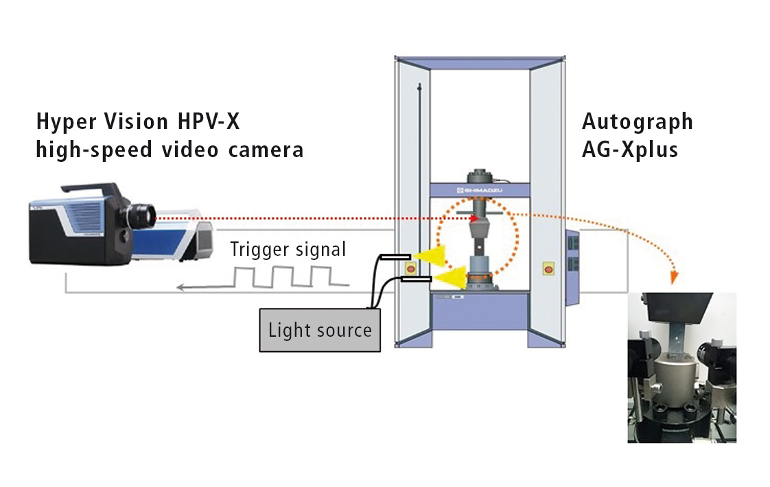 Figure 1: Main unit combined with the HPV-X2 Camera
 Table 1: Test specimen information
Note:
The CFRP laminate board used in the actual test was created by laying up pre-impregnated material with fibers oriented in a single direction.
The [+45/0/-45/+90]2s shown as the laminate structure in table 1 refers to the laying up of 16 layers of material with fibers oriented at +45°, 0°, -45°, and +90° in two-layer sets.
Testing machine creates signal for camera
In this test, the change in load occuring during specimen fracture was used to trigger the HPV-X high-speed video camera. Specifically, the AG-X plus precision universal testing machine was configured to generate a signal when the test force on the specimen reaches half the maximum test force (referred to as Maximum test force in figure 2), with this signal being sent to the high-speed video camera. Static tensile testing and fracture observation were performed according to the conditions shown in table 2. A test force-displacement plot for the open-hole quasi-isotropic CFRP (OH-CFRP) is shown in figure 2a. A test force-time plot during the occurrence of material fracture is also shown in figure 2b.
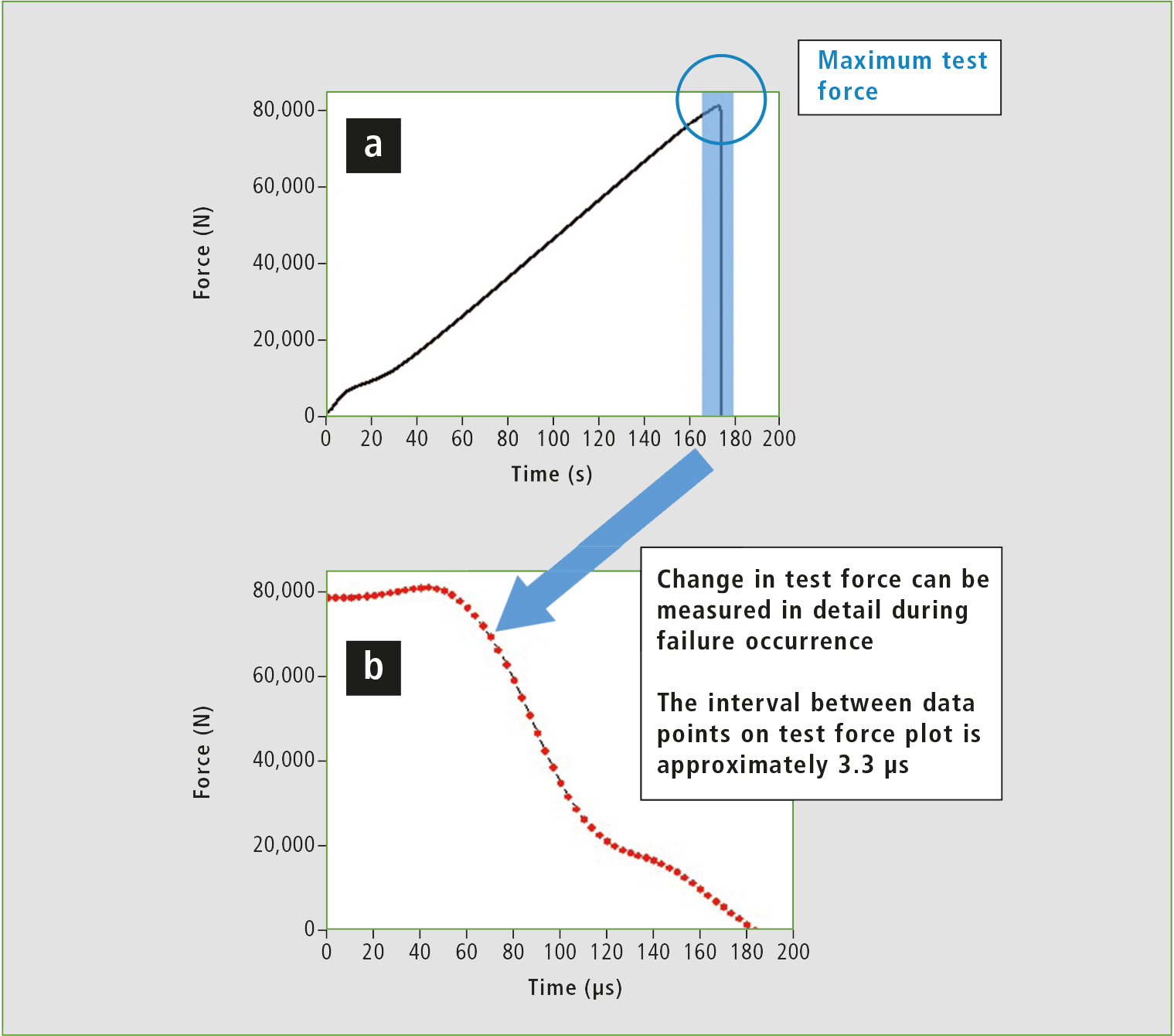 Figure 2: Test graphs
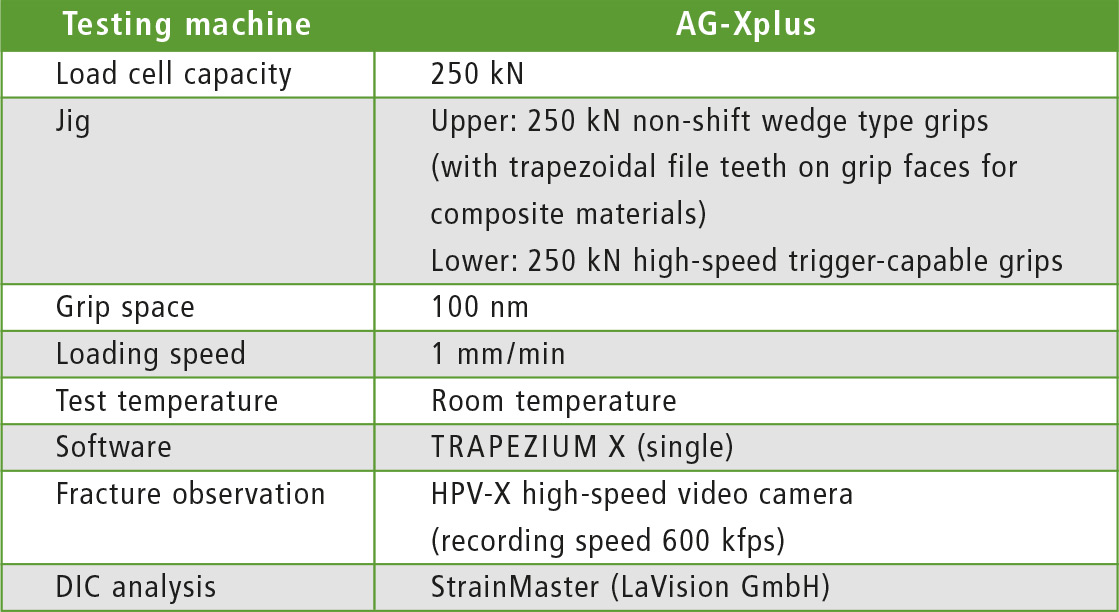 Table 2: Test conditions (*fps stands for frames per second. This refers to the number of frames that can be captured in one second).
Figure 2a can be interpreted to show that the specimen fractured at the moment it reached maximum test force, at which point the load on the specimen was suddenly released. This testing system can be used to perform high-speed sampling to measure in detail the change in test force in the region of maximum test force. The time interval between data points on the test force plot in figure 2b is 3.3 µs.
Images 1 through 8 in figure 3 capture the behavior of the specimen during fracture around the circular hole. Image 1 shows the moment cracks occur in a surface +45° layer. In this image, the tensile load being applied is deforming the circular hole, with hole diameter in the direction of the load of approximately 1.4 times that perpendicular to the load. In image 2, cracks occurring around the circular hole are propagating along the surface +45° layer. In images 3 through 6, a substantial change can be observed in the external appearance of the specimen near the end of the crack propagating to the bottom right from the circular hole. This suggests that not only the surface layer, but internal layers are also fracturing. Based on the images of the same area and the state of the internal layers that can be slightly observed from the edges of the circular hole in images 7 and 8, the internal fracture has propagated quickly in the 18 µs period between images 3 and 8.
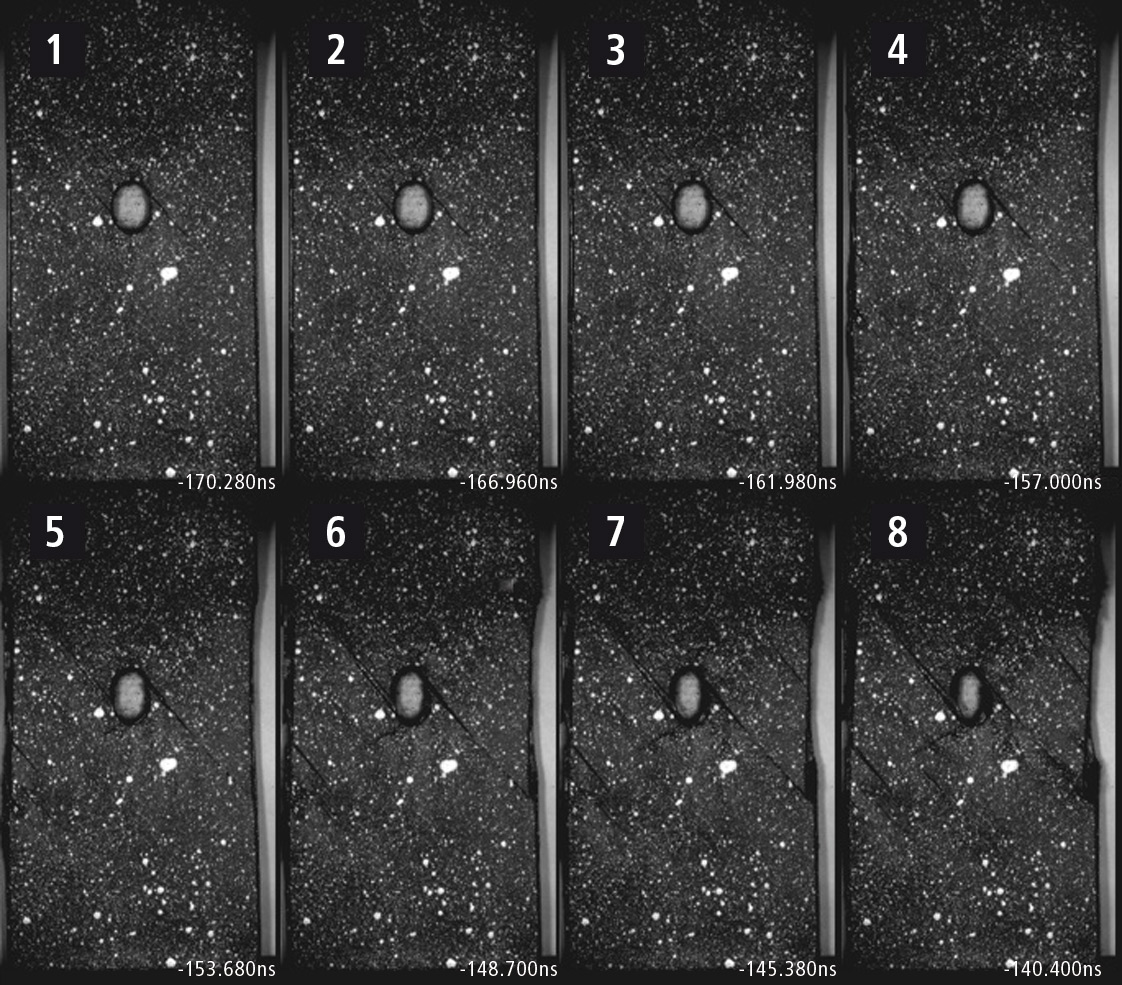 Figure 3: Observation of fracture
Digital Image Correlation (DIC) analysis
DIC analysis performed on the fracture observation images of figure 3. Black signifies areas of the surface layer of the specimen under little strain, and red signifies areas under substantial strain. Looking at images 1 through 4 (in figure 4), it can be seen that strain around the circular hole is focused diagonally toward the top-left (-45 °) and toward the bottom-left (+45 °) from the circular hole. Images 5 through 8 show the focusing of strain diagonally toward the bottom-right (-45 °) and toward the top-right (+45 °) from the circular hole in areas where it was not obvious in images 1 through 4. This shows that an event is occurring in the surface layer of the specimen that is similar to the process of fracture often seen during tensile testing of ductile metal materials, i.e. crack propagation in the direction of maximum shear stress.
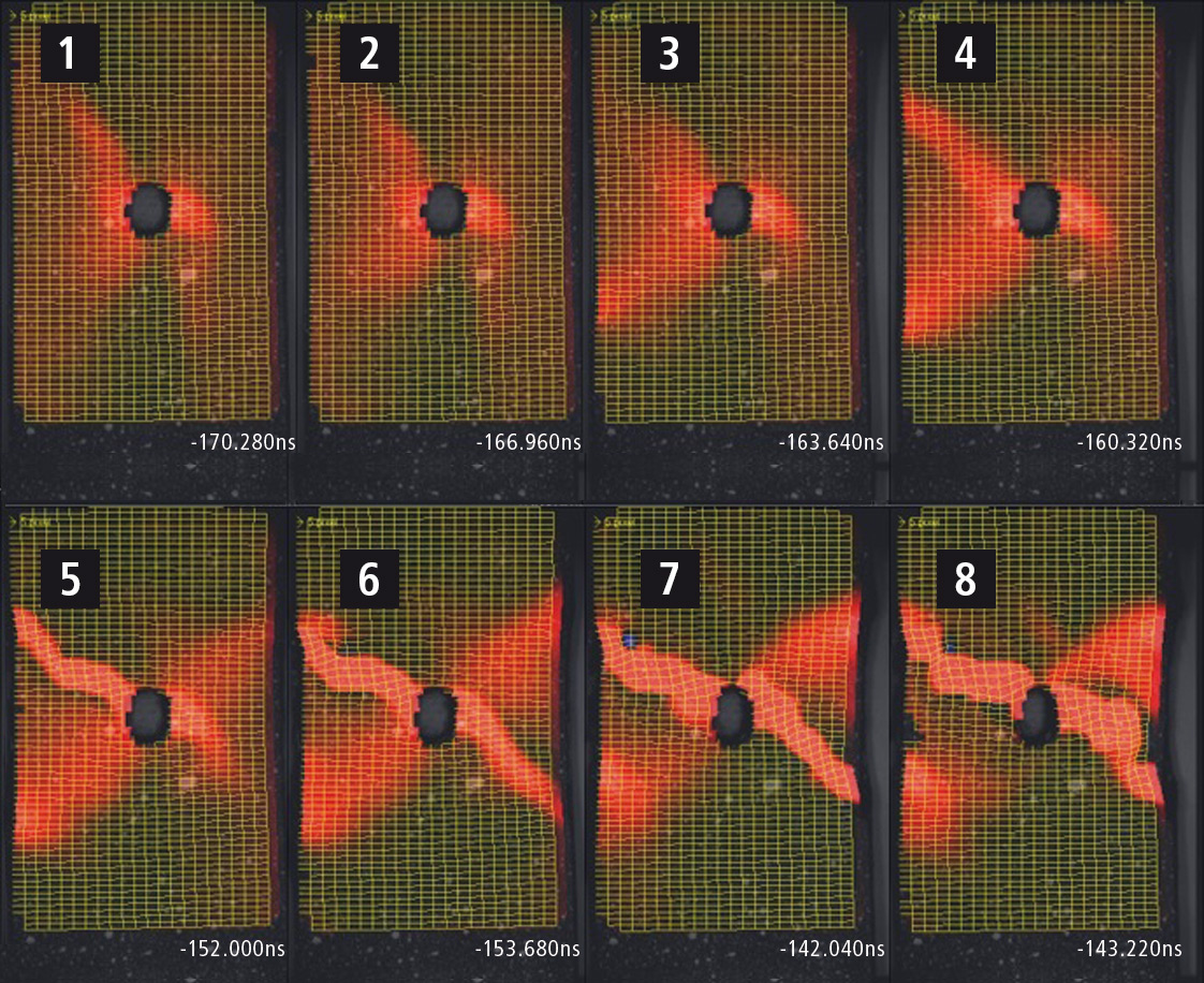 Figure 4: Observation of fracture (DIC analysis)